|
Hurricane IIA, IIB, IIC, IID and IV PILOT'S NOTES
Air Publication 1564 B
British Air Ministry, September 1943
INTRODUCTION
The Hurricane Mks.II and IV are each fitted with a Merlin 20 engine and a Rotol 35° propeller. The Mks. IID and IV are low-level attack versions of the earlier Marks and are equipped to carry various alternative armaments. The aircraft controls, including the undercarriage, flaps and brakes are identical with those on Mark I aircraft.
FUEL, OIL AND COOLANT SISTEMS
Fuel tanks (See Figs.5 and 5A).-
(i) Main and Reserve tanks.- The main tanks are housed within the centre section, one on each side of the fuselage, and a reserve tank is carried between the fireproof bulkhead and the instrument panel. Fuel is delivered to the engine by an engine-driven pump. These tanks are self-sealing and their effective capacities are as follows:
Main tanks: .......33 gallons each.*
Reserve tank: ......28 gallons.
To meet the possibility of engine cutting due to fuel boiling in warm weather at high altitudes, thesa tanks can be pressurised (operative ubove 20,000 feet). Pressurising, however, impairs the self-sealine of tanks and should, therefore, be used only when the fuel pressure warning light comes on, or when auxiliary drop tanks are used (see below).
(ii) Auxiliary tanks: When not fitted with under-wing armament or containers, a pair of auxiliary tanks may be carried, one under each wing. The types of tank and their capacities are as follows:
Fixed: ..... 44 gallons each.
Drop: ..... 45 or 90 gallons each.
With the exception of some fixed tanks which are used for combat duties, these tanks are non-self-sealing. Fuel in the fixed tanks is delivered to the main tanks by electrically driven immersed pumps, but fuel in the drop tanks is supplied direct to the engine fuel pump by air pressure.
3. Fuel cocks.-
(i) The main fuel cook control (48) on the left-hand side of the cockpit has u spring safety plate which prevents the fuel supply being turned off Inadvertently. The control can only be turned to the OFF position whilst the safety plate is held depressed.
(ii) A switch for the electric pump in each fixed auxiliary tank is fitted on the left-hand side of the cockpit, either just above the elevator trimming tab control, or on the lowor part of the electrical panel.
(iii) The fuel cock control (73) and jettison lever (74) for the drop tanks are mounted together on the right-band side of the cockpit, below the windscreen de-icing pump. The cock control has three positions: OFF, PORT and STARBOARD. The pressurising cock must be turned on when the tanks are used. The jettison lever is pulled down to jettison both tanks simultaneously, but cannot be moved until the fuel cock is set to 0FF. When the lever is operated, the air pressure supply is autocratically cut off.
(iv) The tank pressurising cock (22) is fitted on the left-hand side of the cockpit, below the throttle quadrant, and is marked ATMOSPHERE and PRESSURE.
4. Fuel contents gauge.- A gauge (49) on the rignt-hand side of the instrument panel indicates selectively the contents of each of the three main tanks. A switch unit (46), comprising a combined selector and pushbutton, is fitted above the gauge.
5. Fuel pressure warning light.- The warning light (50) on the right-hand side of the instrument panel comes on if the pressure drops to 6 lb./sq.in.
6. Oil system.- The self-sealing oil tank, which has an effective capacity of 9 gallons, forms the port leading edge of the centre section. The oil passes through a filter before entering the engine and then through a cooler inside the coolant radiator. Pressure (54) and temperature (53) gauges are fitted on the instrument panel. When 90-gallon fuel drop tanks are carried, an auxiliary oil tank of 4 gallons capacity is fitted behind the seat, the cock control for which is on the left-hand side of the seat, above the radiator flap control quadrant.
7. Coolant system.- The system is thermostatically controlled, the radiator being by-passed until the coolant reaches a certain temperature. The header tank is mounted on the fireproof bulkhead and is fitted with a pressure relief valve. The air flow through the radiator is controlled by a flap lever in the cockpit.
* The fuel capacities are given in Imperial gallons.
- 1 Imperial gallon=4.546 L ; 1 US gallon=3.785 L
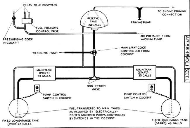
Fig 5. Fuel system diagram - with fixed long-range tanks
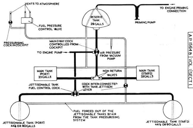
Fig 5A. Fuel system diagram - with jettisonable long-range tanks
MAIN SERVICES
8. Hydraulic system. - An engine-driven hydraulic pump supplies the power for operating the under-carrlage and flaps. The system is automatic, selection of the desired operation of the undercarriage or flaps, by means of the selector lever, being sufficient to commence the operation. A handpump (71) is provided for use In the event of engine failure or engine-driven pump failure.
9. Electrical system.- A 12-volt generator, controlled by a switch (3) on the left-hand side of the cockpit, supplies an accumulator which in turn supplies the whole or the electrical installation. There is a voltmeter (31) on the left-hand side of the cockpit, and a red light (36) marked POW?R FAILURE on the instrument panel comes on when the generator is not charging the accumulator.
10. Pneumatic system.- The wheel brakes and the gun-firing mechanism are operated pneumatically, air being supplied by an engine-driven compressor and stored in a cylinder at a maximum pressure of 300 lb./sq.in.
AIRCRAFT CONTROLS
11. Flying controls. - The control column is of the spade-grip pattern and incorporates a gun-firing pushbutton and the brake lever. The rudder bar is adjustable for leg reach by means of a star-wheel midway between the two pedals.
12. Trimming tabs.- The elevator trimming tabs are controlled by a handwheel (24) on the left-hand side of the cockpit and an indicator is fitted next to it. Forward rotation of the hand-wheel corrects tall heaviness. The automatic balance tab on the rudder can be set for trimming purposes by means of a small control wheel (53) on the left-hand side of the cockpit, which is turned clockwise to apply right rudder.
1 >>
| 


