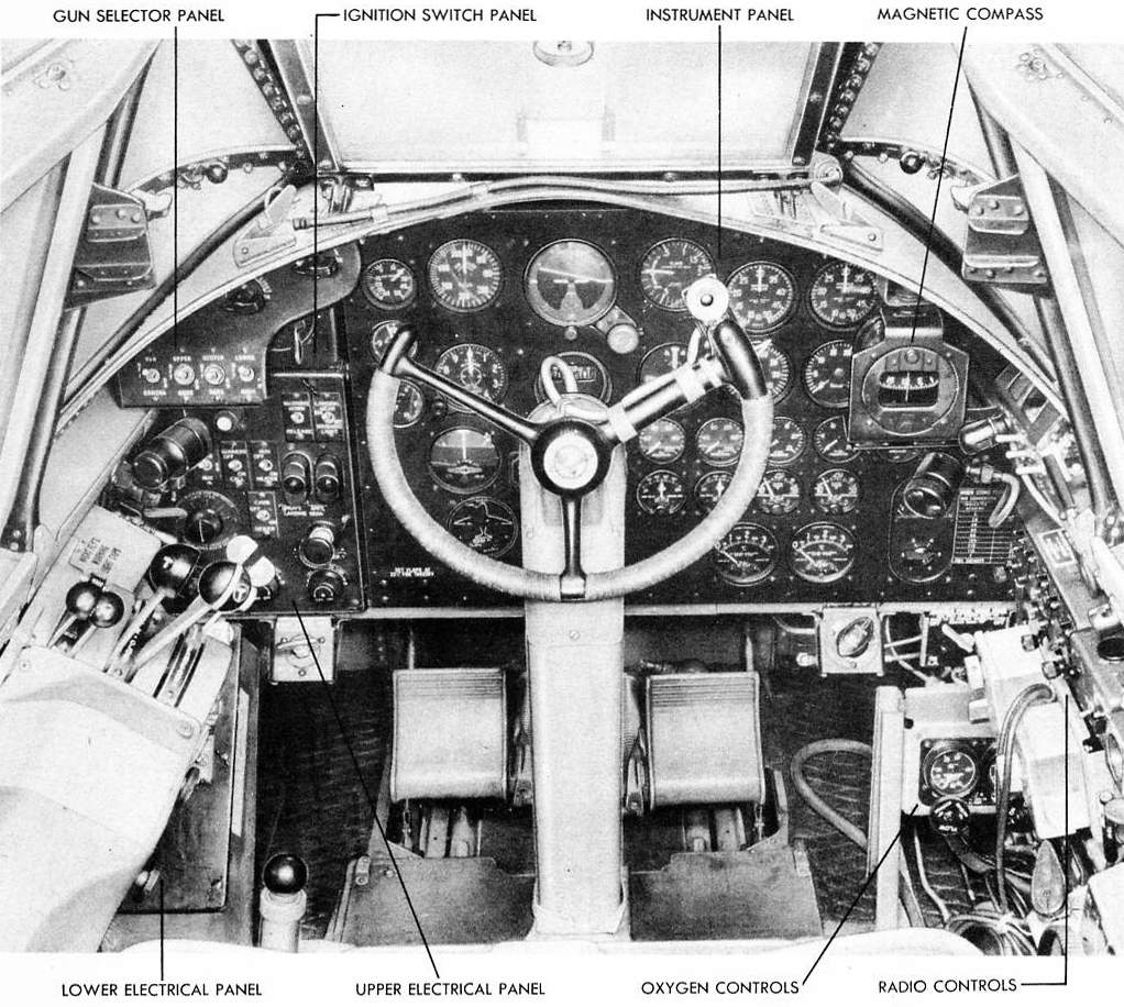
Figure 160 - PILOT'S COMPARTMENT
14. INSTRUMENTS.
a. DESCRIPTION.
(1) GENERAL. - All instruments are fluorescent lighted. The following are mounted on a shockproof instrument panel located in the pilot's compartment. (See figures 160 and 161.)
Air-speed indicator
Altimeter
Carburetor mixture temperature indicators (two)
Clock
Compass
Engine temperature indicators (two)
Flight indicator
Fuel pressure gages (two)
Fuel quantity indicator
Hydraulic pressure gage
Indicator unit for landing wheels and flaps
Manifold pressure gages (two)
Oil pressure gages (two)
Oil temperature indicators (two)
Outside air thermometer
Rate of climb indicator
Suction gage
Tachometers (two)
Turn and bank indicator
Turn indicator |
Pioneer, 1426-4T
Pioneer, 1582-2M
Lewis, 47ACX
AAF Specification 94-27970, type A-ll
IN-4A
Lewis, 17AT7K
AN-5736-2 (Sperry 647900)
AAF Specifications 94-27919 type C-13
EA47W-6
AAF Specification 94-37922, type E-4
G.E., 8DJ4PBX
U.S. Gage, AW-2 3/4-14F
AAF Specification 94-27917, type B-8A
Lewis, 47AC2J
U.S. Gage, AW-1 7/8-20-CG
Pioneer, 1634-1M
AAF Specification 94-27336, type F-4
Weston model, 545, type 56P
AAF Specification 27348, type A-11
AN-5735-2 (Sperry 647910) |
(2) INSTRUMENT PANEL. (See figure 161.) -Ashockproof instrument panel is mounted in the pilot's compartment and held in place by four bolts that are inserted through rubber shock mountings.

Figure 161 - INSTRUMENT PANEL
ITEM
NO |
PART NUMBER |
PART NAME |
NO
REQ |
1
2
3
4
5
6
7
8
9
10
11
12
13
14
15
16
17
18
19
20 |
AAF SPEC. 94-27970 TYPE A-1 1
U. S. GAUGE AW-1 7/8-20CG
PIONEER 1426-4T
PIONEER 1555-21
AN-5736-2 (SPERRY 647900)
AAF SPEC. 27348 TYPE A-l 1
PIONEER I634-IM
U. S. GAUGE AW-2M-14F
WESTON MODEL 545 TYPE 56L
AAF SPEC. 94-27917 TYPE B-8A
AAF SPEC. 94-27922 TYPE E-4
AAF SPEC. 94-27336 TYPE E-4
IN-4A
GE8DJ4PBX
AN5735-2 (SPERRY 647910)
AAF SPEC. 94-27917 TYPE B-8
LEWIS 47AC2J
LEWIS 17AT7K
LEWIS 47ACX
EA47W-6 |
CLOCK
THERMOMETER, OUTSIDE AIR
NDICATOR, AIR-SPEED
ALTIMETER
INDICATOR, FLIGHT
INDICATOR, TURN AND BANK
INDICATOR, RATE OF CLIMB
GAUGE, MANIFOLD PRESSURE
TACHOMETER
GAUGE, FUEL PRESSURE
GAUGE, HYDRAULIC PRESSURE
GAUGE, SUCTION
COMPASS, RADIO
NDICATOR, LANDING GEAR AND FLAP POSITION
INDICATOR, TURN
GAUGE, OIL PRESSURE
INDICATOR, OIL TEMPERATURE
INDICATOR, ENGINE TEMPERATURE
INDICATOR, CARBURETOR MIXTURE TEMPERATURE
NDICATOR, FUEL QUANTITY |
1
1
1
1
1
1
1
2
2
2
1
1
1
1
1
2
2
2
2
1 |
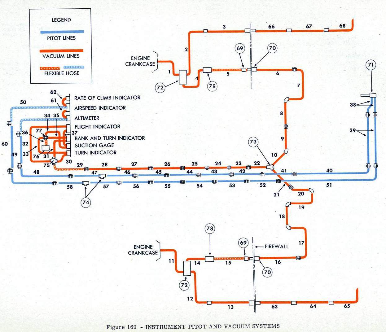
(3) PITOT AND VACUUM SYSTEMS. (See figure 169 )

Figure 169 - INSTRUMENT PITOT AND VACUUM SYSTEMS

a) A pitot static and a pitot pressure line extend from a pitot head at the top of the vertical stabilizer along the left side of the fuselage to tees behind the pilot's instrument panel. A line from each tee connects to the air-speed indicator and altimeter on the panel. A drain tee is installed in each line aft of Station 75.
(b) The vacuum system consists of lines which extend from vacuum pumps on each engine through the nacelle and inner wing to a "Y" fitting at the right side of the fuselage. From this point they continue forward along the right side of the fuselage to the suction regulator behind the instrument panel. Three lines extend from the regulator to the throttle valve, flight indicator and turn indicator, respectively. The bank and turn indicator and suction gage obtain vacuum from the throttle valve and flight indicator, respectively.

(4) COMPASSES. - There are two compasses in the pilot's compartment. One is the magnetic type and the other is a radio compass. See paragraph 22, this section, for information on the radio compass.
(5) TACHOMETER GENERATOR (See figure 164.) - A small generator mounted on the fuel pump accessory drive on the rear of the engine supplies the necessary electrical current to actuate the tachometer.
(6) VACUUM PUMP. (See figure 162.) - To supply vacuum for the operation of gyroscopically actuated instruments, a vane-type vacuum pump operates in the oil system. The vacuum pump takes its small oil requirements from the engine accessory section on which it is mounted by four stud bolts. The pump is gear driven as an engine accessory. Incorporated in the vacuum line to the instruments are four valves. A suction relief valve is located at the engine accessory section forward of the fire wall on the inside of the nacelle. It controls Dow in one direction in the event of backfire of the engine.

<< | >>>
|