EQUIPMENT
(1) FUEL CONTAINERS.
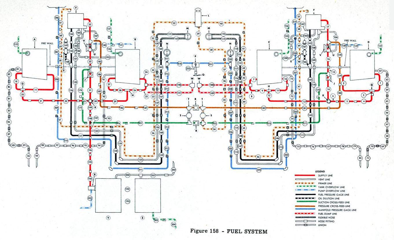
(a) FILLING. (See figure 21.) - Each inner wing has two compartments (one on each side of the nacelle), which enclose self-sealing fuel containers. Each inboard fuel container has a capacity of 136 U.S. gallons (113 Imperial gallons); each outboard fuel container has a capacity of 64 U.S. gallons (53 Imperial gallons). The filler for the inboard fuel container is located on the upper surface of the wing just inboard of the nacelles and aft of the front shear web. Filler for the outboard fuel container is located on the upper surface of the wing just aft of the front shear web near the outer end of the inner wing.


Oil System
a. DESCRIPTION.
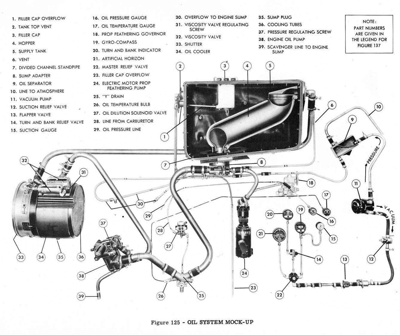
(1) GENERAL. (See figures 125.) - Each engine and its propeller has an independent pressure feed oil system. Two oil supply containers are located in the inner wings forward of the main spar on the center line of the nacelle. Filling, removal,and installation of the oil supply containers are accomplished through access doors and cover plates on the upper wing surface. Supply lines to the engine pump and to the propeller feathering pump lead from a sump adapter which is attached to the bottom of the oil supply container. The sump adapter protrudes beneath the wing and is accessible forward of the fire wall. The oil container filler cap is so constructed that it regulates the ratio of oil supply to air space. A baffled hopper reduces oil foaming and minimizes the turbulence of flow. The hopper also vents air in oil returning from the engine. Pressures set up in the oil container by the foaming of return oil, or by volatilized gases due to oil dilution or burned oil are released by vent lines. Vents lead from both the inboard and outboard upper walls of the supply container to the engine, and assure venting while the oil container is inclined. Excess of oil in the filler neck overflows by line to atmosphere. An engine pump supplies oil under pressure to each engine, and filters and returns the oil through the cooler to the supply container. An oil temperature regulator, referred to as the oil cooler, is mounted in each nacelle, inboard. An electrically driven pump supplies oil at proper pressures directly from the supply container to a propeller feathering governor. For cold starts a solenoid operated valve controls injection of gasoline into the oil at the "Y" drain leading to the engine supply.

Hydraulic System


<< | >>
|